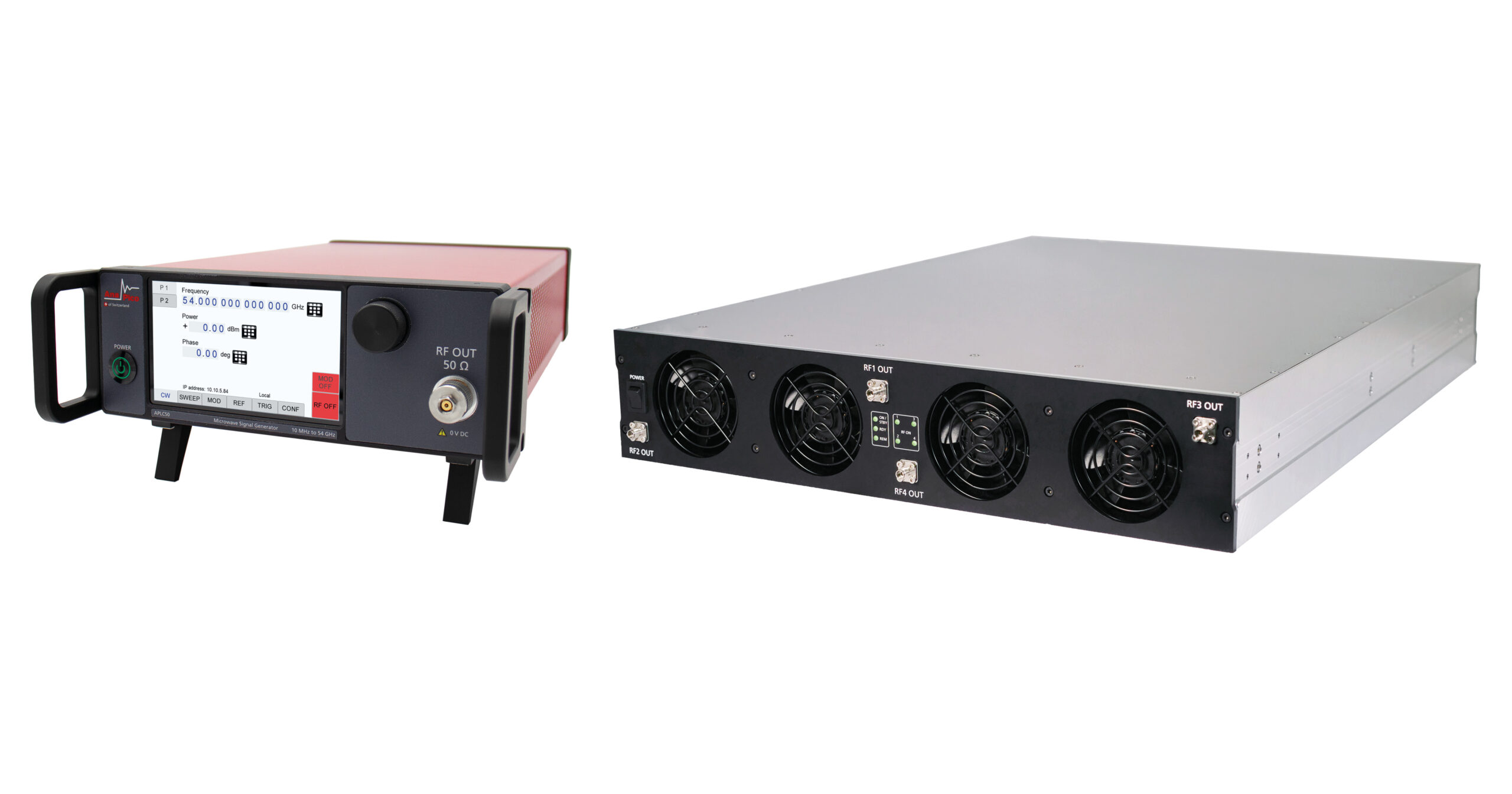
APLC
The demand for metrology-grade signal generators in high-precision T&M applications necessitates a comprehensive set of advanced performance characteristics. These include high output power, low phase noise, fast amplitude and frequency switching, high spectral purity, and precise modulation capabilities, among others. Moreover, the compact design and low power consumption are important for the development of multi-channel phase-coherent signal sources, crucial in applications such as radar and beamforming testing, MIMO system evaluation, and quantum computing research.
Addressing these exacting requirements, AnaPico has recently unveiled the APLC series of single- and multi-channel analog signal generators, encompassing a frequency range spanning from 9 kHz to 54 GHz, having such a comprehensive suite of performance features in a single product line.
Some key specifications are summarized in the table below.
Frequency range | 9 kHz and 10 MHz to 12.75, 20, 40 and 54 GHz |
Number of channels | 1 to 4, customer-configurable |
SSB Phase noise at 10 GHz | @ 20 kHz offset: -130 dBc/Hz |
Harmonics and non-harmonics | -50 and -85 dBc |
Reference frequency aging | 0.02 ppm per year |
Switching speed | 15 μs |
Power range | -120 to +25 dBm |
Analog modulations | AM, FM, PM |
Pulse modulation | ON/OFF ratio: 100 dB; Min. pulse width 10 ns; Rise/Fall time: 3 ns |
Multi-channel models | Phase coherence; Phase-coherent switching |
SIGNAL GENERATOR ARCHITECTURE
Figure 1 is a simplified block diagram of the device. To meet the demanding specifications for frequency switching speed while maintaining low phase noise, a Voltage-Controlled Oscillator (VCO) and Direct Digital Synthesis (DDS) were chosen as the foundation for frequency synthesis. The primary reference signal for the entire system is a high-frequency clock directly derived from the internal low-noise 100 MHz Oven-Controlled Crystal Oscillator (OXCO).

Figure 1: APLC simplified block diagram
To effectively suppress spurs in the system, we utilized a technique called synthesis with variable reference. The APLC’s Phase-Locked Loop (PLL) system offers two degrees of freedom, allowing for adjustments to either the DDS synthesizer frequency or the REF1 reference frequency in small increments. By employing both methods alongside a well-designed frequency plan, we can minimize unwanted spurs.
The “DDS Upconversion Expansion” block consists of various multipliers and dividers to adjust the REF1 and REF2 frequencies as required. The output stages, comprising multipliers, fractional dividers, amplifier stages, and a tunable Very Low Frequency (VLF) filter, represent a classic approach to achieving low harmonic levels across a broad frequency range while maintaining high signal power.
EXECELLENT FREQUENCY STABILITY AND PHASE NOISE
The Phase noise as a critical parameter often determines how well a signal generator suits an application. Ensuring good phase noise in all offset frequency ranges, and yet keeping the agile switching feature was the top focus of our APLC series.
In addition to a standard 100 MHz reference, APLC can have optionally more stable and low drift OCXO-based 10 MHz references (options LN and LN+). Locking the 100 MHz oscillator significantly reduces the close-in (0 to 100 Hz) phase noise level. The annual aging rate is improved to the level of 20 ppb.
The excellent phase noise performance of the 100 MHz reference, paired with the innovative frequency synthesis circuitry, ensures the remarkably low phase noise level in the mid-offset range.
In the far-end offset range, no YIG-like filtering mechanism has been used on purpose, like AnaPico’s other signal sources, allowing for the signal source to be rapidly switchable.
Figure 2 illustrates the single-sideband (SSB) phase noise performance of the APLC signal generators equipped with option LN. Excellent phase noise performance is achieved across the entire offset range and the signal frequency range up to 54 GHz. As can be seen from the measured results, at a carrier frequency of 10 GHz, APLC reached -90 and -130 dBc/Hz at 10 Hz and 20 kHz offset frequencies, respectively.

Figure 2: SSB phase noise of APLC analog signal generators with option LN
STRONGLY SUPPRESSED HARMONICS AND NON-HARMONICS
The signal purity, characterized by harmonics, sub-harmonics, and spurious signal levels, is another crucial aspect related to the signal quality. Low levels of all types of unwanted signals are essential to minimize signal distortion, to incur less and lower-level interference signals, and thus to improve test system accuracy and sensitivity.
With a combination of circuit design approaches, filtering and frequency plan optimization, APLC signal sources feature leading-edge performance levels for all harmonic and non-harmonic signal levels. At 10 GHz, for example, the harmonics and non-harmonics are as low as -50 and -85 dBc.
HIGH-OUTPUT POWER
In the microwave frequency range, achieving high output power is crucial. To address losses experienced at higher frequencies, we have opted to install multiple output amplifiers, covering the entire frequency range from kHz to 54 GHz. With this architecture, power output within the 30 to 40 GHz frequency range reaches approximately 22 dBm, while in the 40 to 54 GHz range, it still exceeds 15 dBm. This enhancement ensures robust power levels across a broader spectrum with decent harmonic rejection, meeting the demanding requirements of microwave applications.

Figure 3: Maximum output power of APLC SGs
PULSE MODULATION PERFORMANCE
In applications such as radar testing, the quality of pulsed continuous wave (CW) signals is paramount for performance verification. The signal generator must be able to generate pulses with narrow widths and fast rise and fall times at a high repetition rate.
For pulse modulation, attenuators and switches are commonly used to achieve fast transition times. To achieve a high ON/OFF ratio and faster operation, multi-stage switches are used in the APLC series. We achieved the ON/OFF ratio of 100 dB, and the pulse width of 10 ns, with a typical rise/fall time of about 2 to 3 ns. Figure 4 shows two such pulses with 30 ns width and at 10 and 50 GHz, respectively.
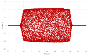
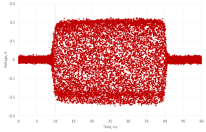
Figure 4: 10 GHz and 50 GHz pulses with 30 ns width
FAST SWITCHING
The APLC, with its sophisticated design architecture, also optimized for frequency agility, achieves a best-in-class (analog signal generators) switching speed of typically 15 μs. This rapid switching speed is particularly meaningful in automated test equipment (ATE) systems, where faster switching can significantly accelerate the verification process. The APLC series stands out as the first model to overcome the trade-off between phase-noise and spur levels and switching speed, offering unparalleled performance in both aspects simultaneously.
Another important application for very frequency-agile generators is the generation of fast-stepping radar pulses or fast frequency-hopping signals. Moreover, multichannel APLC signal generators with intrinsic phase coherence and optional phase memory features can be cost-efficiently used to generate multi-stream signals for antenna arrays, used for radar and beam-forming testing.
PHASE COHERENCE AND PHASE MEMORY
The multi-channel APLC-X signal generators feature strong phase coherence and unique phase-coherent switching. While the use of a common stable and accurate frequency reference for digital signal synthesis in all channels is the fundament for the phase coherence, the careful thermal-mechanical design ensuring very similar ambient conditions for all channels and leading to similar channel drift behavior further raises the phase coherence level. Moreover, with an AnaPico proprietary high-frequency synchronization mechanism among multiple devices, it extends the phase coherence characteristics to truly multi-channel systems.
Figure 5 illustrates the measured phase coherence of APLC-X. When setting two channels of an APLC-X device to the same 38 GHz frequency, a relative phase difference variation of 1 degree (RMS) can be measured over a period of 10 hours. When measuring the same on two channels from 2 different and synchronized APLC-X devices, very similar phase coherence behavior can be observed.

Figure 5: Channel-to-channel phase difference variation at 38 GHz and over 10 hours
Further to the phase coherence feature embedded in the basic devices of APLC-X, AnaPico also implemented the unique phase-coherent switching function on the APLC-X platform. With this optional feature (option PHS), APLC-X can memorize the relative phase constellations among the multiple channels and depending on the signal frequencies. The memory function is still effective even when the signal channels are switched off and turned on again. In Figure 6, one can see that the relative phase constellation between the channels at a certain frequency is always the same, even after channel frequency changes. In other words, the phase-coherent switching or phase memory ensures deterministic and reproducible phase relationships among multiple channels.
 Figure 6: Phase-coherent switching with APLC-X
The phase coherence and phase-coherent switching are enabling features of multiple applications. In the antenna array-based radar and smart beamforming testing systems, it allows the systems to remember important angle information. In quantum computing instrumentation systems, these features are essential for the formation of consistent qubit states, the generation of phase-aligned qubit manipulation signals, as well as to reduce the system calibration requirement thus shortening the system latency.
COST EFFICIENT AND EDGE-CUTTING PERFORMANCE
In comparison to other commercially available analog signal generators in the market, those described performance points of the APLC series such as phase noise, spectral purity, pulse ON/OFF ratio, switching speed, etc. are all characteristics of the high-price class instruments. Developing and supplying high-performance and yet cost-efficient T&M instruments has always been the mission of AnaPico. With this in mind, we often avoid using high-cost and early-phase components and rather apply sophisticated circuitry design, keep the product architecture modular and yet deliver low-redundancy instruments.
APPLICATIONS
Enabled by the above-described features and performance levels, the APLC series can be used in multiple applications.
- RF and microwave component testing
- LO substitution
- Receiver blocking testing
- ADC characterization
- Instrument and system calibration
Especially, the multi-channel phase coherent APLC signal generators are suitable for:
- Multi-channel and/or MIMO receiver testing
- High-sensitivity intermodulation testing
- Generation of qubit manipulation signals in quantum computing
- High throughput automated testing
- Smart antenna and beamforming testing
- Radar and EW testing
CONCLUSION
AnaPico’s APLC series analog signal generators represent the first signal sources in the market with a remarkable feature combination: ultra-low phase noise, fast frequency, and amplitude switching, very low harmonics and spurs, clean pulse modulation, compact design, low power consumption, and yet at an affordable price level. Thanks to its innovative design, the device can be operated either from main power or in the field from an external power bank. AnaPico is the first manufacturer to make this level of generator performance available for use outside the laboratory.
The APLC-X series offers a compact and high-performance solution for generating multi-channel phase-coherent signals. By synchronizing multiple APLC-X generators through an AnaPico proprietary high-frequency clock mechanism, users can tailor their setups to meet specific needs regarding the number of channels as well as RF and microwave frequency bands, and at the same time keeping the strong phase coherence and the unique phase memory.
For further information about our product range contact our support team.